Overview
Suspensions are a critical element in racing, right? We see F1, IMSA, NASCAR, etc with teams of suspension and shock experts. When I was building 103 I wanted to stay within the vintage spirit and use stock dampers (i.e., shock absorbers) but I also had an eye on extracting the best performance possible…what racer wouldn’t?
After consulting other Healey racers, I purchased a stock dampers that had been professionally rebuilt and modified with external valves. This allowed the stiffness of each front dampers to be adjusted from outside the damper (versus pulling the damper off, draining it, rebuilding, adjusting, etc…argghhh), easily reached from the engine compartment. Same with the rear dampers except you access the adjustment valve from under the car.
I asked my fellow racers a lot of questions about improving damper performance. You would think I asked how long is a piece of string!!! No two answers seemed alike. Don’t do anything, they work great. Use thicker shock fluid to increase damping. Use thinner fluid to decrease damping. Set them to a setting and, if you like it, leave it that way….if you don’t like it then adjust, test, adjust, test…and so on, and so on, and so on.
I was largely unimpressed by the large variety of answers so, having a data system, I took more red pills than Neo in the Matrix and dove down the rabbit hole. The following overview summarizes this adventure (note, I do have a lot further to go).
Goals
After reading several articles and a spectacular book by Jorge Segers (Analysis Techniques for Racecar Data Acquisition), I identified some specific goals.
- First and foremost I needed to address any major over or understeer problems, primarily by controlling the speed of vehicle weight transfer both into and out of corners.
- I needed to to control the overly happy rear end of the car during heavy braking.
- The first step to get there was simply to get an understanding of how the dampers were behaving.
- The second step was to have the front dampers behave similar to each other and the rear dampers behave similar to each other.
- The third step is then to address any over and understeer.
At this point I think I have a good grasp on steps one and two, which is summarized below.
General Characteristics
Austin Healey’s use lever-arm dampers instead of tube dampers which can make it challenging to apply even basic and commonly used damper behavior descriptions. For example, to calculate and characterize damper movement, most often a linear potentiometer is mounted near a damper (tube type damper), preferably parallel to a damper body to record the damper’s linear movement (see figure below). The hub assembly is moved up an down and then the distance change in the damper is divided by the distance change in the potentiometer. This results in a motion ratio (MR) that can identify hub/wheel position by simply multiplying the potentiometer value by MR.
Except lever-arm dampers don’t have a point at which they compress like a tube style damper. In addition, lever arm dampers do not exhibit linear movement like a tube style damper because the shock arms move in an arc around the pivot point on the shock body (see figure below).

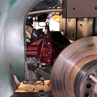
My solution was to mount the potentiometers with one end attached to a point on the shock arm and the other end on a fixed object (like the chassis or a bracket attached to the chassis). See figure below for potentiometer mounting on rear damper. I then calculated the MR at the point where the damper arm and the king pin intersect, essentially the upper trunion.
At the very least I feel like I have standardized between all corners of the car what I am measuring, essentially movement at the trunion at the front which is the same as movement of the hub/rear wheel/tire, and movement of the springpan on the rear which is the same as movement of the rear wheel/tire.
Adjusting Damping Rate
In its stock configuration the damping rate is controlled by small holes inside the damper which dictates the rate of fluid flow from one chamber to another. So, as the damper arm moves up or down slowly, the fluid is forced through the small holes by pistons within the damper body.
The damping rate (i.e., damper stiffness) can be altered a few different ways. First and foremost, just changing out the shock fluid from the normal 20wt oil to 30wt or something in between (but do not exceed 30wt) will increase damper stiffness.
The size of the little holes can also dictate how fast a damper arm can moves. Change the size of those little holes and damping stiffness can be changed. However, if the damper arm needs to move fast, say as the car go over a sharp bump on the road or you hit a curb, the little holes can’t possibly allow that much fluid to pass. In this case, the pressure of the fluid actually opens a small valve by overcoming the force of a spring. There is a small spring for compression (i.e., bump) and one for extension (i.e., rebound) and they can be adjusted (see links below for great explanations and diagrams).
The size of the small pistons in the shock body that force the oil through the orifice can also be altered to change damping stiffness but, as you can imagine, this requires some serious surgery.
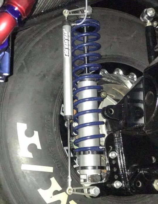
Some racing organizations allow dampers to be modified so that damping rate can be adjusted by an external valve that can be opened or closed to decrease or increase damper stiffness (see figure below). This approach allows racers control of overall damping stiffness much easier than most other other approaches.

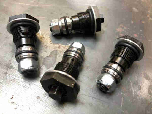
There is a middle ground. AJB Engineering in the UK (see figure below and link at bottom of page) has devised a modification to the stock lever arm damper valve that can be adjusted from the outside of the damper to modify damper stiffness.
There are some other challenges to consider. Adjusting lever arm dampers, either as stock or modified in the ways identified above, may not provide control over advanced damper characteristics, such as having different low and high speed damping stiffness (for either compression or extension). There may be ways to do that…but right now I am focusing on the basics and how to optimize what I have before taking more Matrix red pills and going down a rabbit hole I can’t get out.
Data Collection
Damper movement data was collected on each corner of the car via a linear potentiometer (see figure below, Pegasus Racing and many other sources sell these) that had a 2′ stroke length. The data was collected at 500 Hz (i.e., samples per second) and saved to an AIM EVO4S data acquisition system (see figure below).


Initial Findings
The data presented in the following figures depicts the fastest single lap at the Circuit of Americas at an event in November 2023. The dampers were adjusted prior to several previous events to get them to perform more similarly, so this represents just one longer-term adjustment and tuning step.
The damper position figure below depicts the longitudinal acceleration of the vehicle within the uppermost strip, as measured by the onboard accelerometer in the EVO4S data system. G force is the measurement unit. Pairing this data with the damper data helped to visualize when the vehicle was accelerating and decelerating and how/when the dampers responded.
The data within each damper position strip is raw in that is depicts the change in vertical position of the damper arm (actually the trunion in the front and springpan in the rear). Measurement unit is inches, about 1 inch of movement for compression (numbers greater than 0) and 1 inch of movement for extension (numbers less than 0) from static (0) position. The X axis is time (for a single lap in this example).
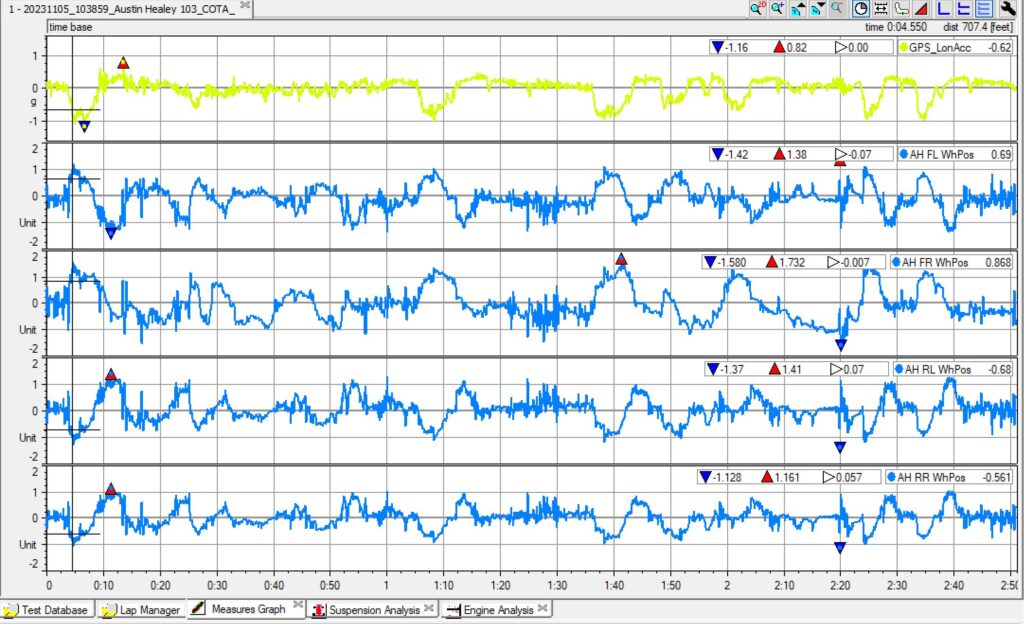
No big surprises…things are at least working as planned. Front dampers compress (i.e., bump) and rear shocks extend (i.e., rebound) under braking and vice versa under acceleration. Left and right dampers are acting opposite (one side compressed, one side extended) in turns.
The damper speed figure below again depicts longitudinal acceleration at the top. Each strip shows the speed of the damper arm (e.g., trunion, springpans) velocity as inches of movement per second (in/s). Again, compression is shown as numbers greater than 0 and extension as numbers less than 0.
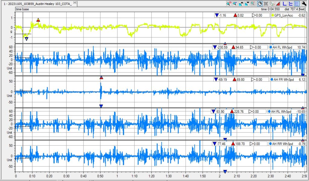
Now we get a bit of valuable information. The first and foremost observation is that the FR damper is significantly more damped than the other corners. This is the first issue to address and will be done by opening the valve on that damper. Some differences can be seen between the other three dampers but it is challenging to determine how similar or dissimilar the differences are.
Frequency Histogram
The real value of the data system is the ability to aggregate and depict data in ways that can help to inform damper adjustments. The following figure again depicts data from each damper. The Y axis in each strip depicts the positive and negative velocity of the damper.
For example, as a car is moving along a very smooth track it is not moving up or down, so the dampers are not moving. Another way to say this is that the damper speed is 0, or at least very near zero. As a car is moving along a very bumpy track the car is moving up and down fast, so the damper arms are moving into and out of compression and extension fast. Another example is when damper arms move fast into compression when a vehicle pitches forward as a driver starts braking.
The Y axis depicts the percent time that a damper spent at each velocity (well, small ranges of velocity because each very small row represents a very small range of velocity). As an example, in the top strip, the FL damper spent about 36% of the time at or very near 0 in/s and only about 1 or 2% at high velocities, like 40 in/s.
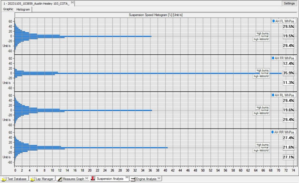
- The most significant observation is that the RF damper spent a significantly greater amount of time at a velocity at or very near 0 in/s compared to the other shocks. So the stiffness of this damper needs to be reduced to make it more similar to the others.
- A second observation is that the FL, RL, and RR were fairly similar to each other. The peaks are at about the same location, the shape is fairly symmetrical (meaning the damper behaves similarly in compression and extension), and the bases are approximately the same width.
- The similar performance of the three dampers can also be seen in the percentages listed in the small boxes on the right side of each strip.. The upper and lower number in each strip indicates the percent of time the damper spent at velocities greater than 3 in/s for compression and -3 in/s for extension. The performance of each dampers in both compression and extension were very similar but also, the dampers performed similarly to each other. I can see just how different the RF shock is compared to the others. It only spent about 23% (12% + 11%) of its time at greater than +3 in/s and lessor than -3 in/s compared to the other dampers which spend nearly 60% at the same velocities.
Next Steps
- The immediate next step is to adjust the RF damper so that it behaves similarly to the other dampers.
- After that, the issue to address is how much damper stiffness is optimal. That is to say, should the stiffness of the dampers be increased so that the dampers spend more time at lower velocities and less time higher velocities (peaks get higher, bases get thinner) or vice versa. The former means the racecar will roll, pitch, and yaw more slowly. This can be a tool to alter vehicle under or over steer into and our of corners.
- As a first step to do that I need to go back and look at the velocity of specific dampers at specific times and determine how this relates to any vehicle handling issues (e.g., corner entry and exit over and understeer). I will likely create a new investigation page to explore this.
Now, more Matrix red pills and further down the rabbit hole I go.
Supporting Docs
- A Guide to Dampers
- A Guide to Over and Understeer (AIM Data)
- The MG Experience – Refreshing your MGB Shocks
- MGA Guru – Valving for Armstrong Shocks
- MGA Guru – Adjustable Shocks
- The MG Experience – Adjustable Shocks
- TR Register Australia – What a Shocker (little springs info)
- A.J.B. Engineering – Adjustable Shock Valves