
Arghhhh!!!!!!!
Have you ever worked on a project so long and so many times that your threshold for patience is exceeded? That threshold seems to be when the number of four letter words used far exceeds the number of non-four letter words. Well, I am there. I would rather remove a tooth using shards of glass than continue to adjust my carbs. #103 uses three 2″ SU carburetors which are absolutely beautiful to look at but it also means three times the hassle!
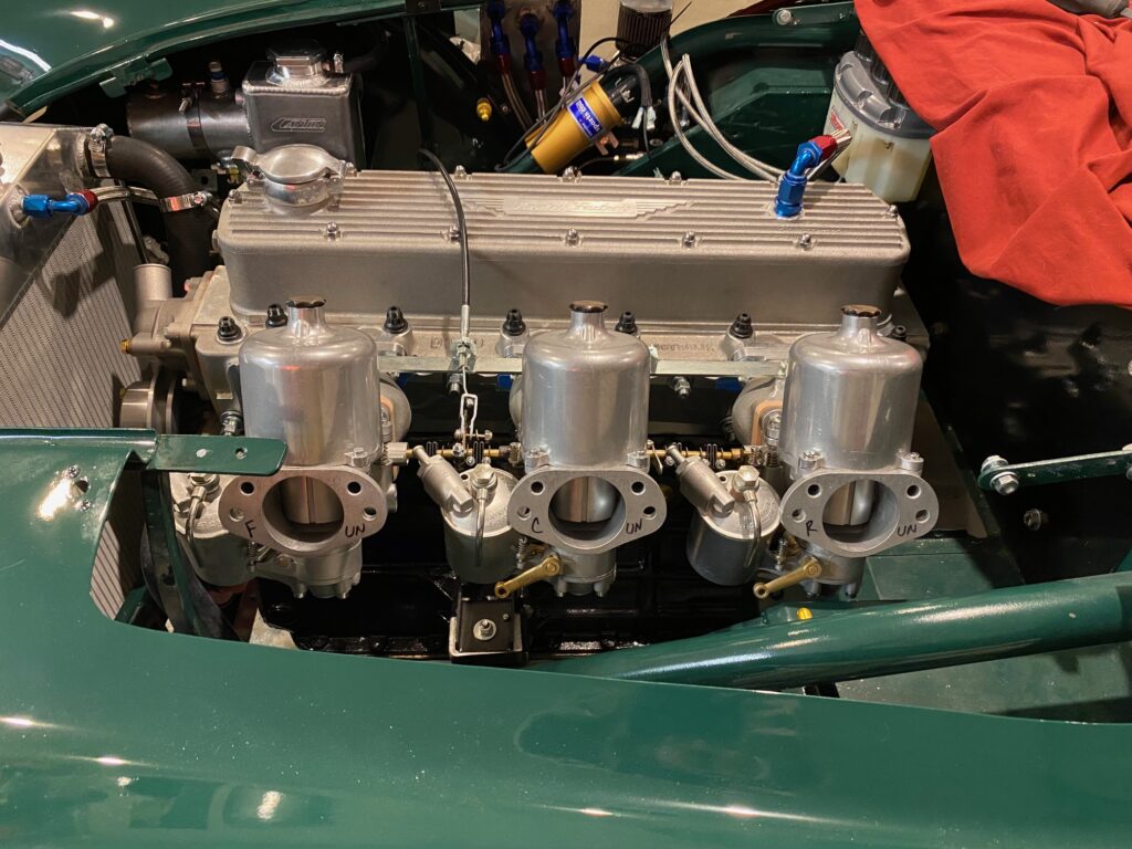
There are big issues to tackle like trying to get the fuel level at just the right height in the jet and keeping it there reliably, determining what needle size not only works but is optimal, and adjusting mixture.
These items are all related to the goal of feeding the engine with just the right amount of fuel. To much fuel (the car is said to run rich) and power will suffer. To little fuel (run lean) and the temperature of engine components could rise to the point where devastating problems can occur…like burned valves or melted bits. If this happens you might as well buy roses for your spouse before breaking the news, get out the checkbook for the engine builder’s house and boat payments, and start crying in your beer. Just the right amount of fuel creates the most power without damaging the engine.
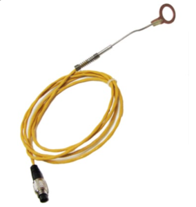
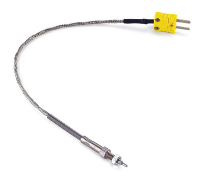
But how do you know when the engine is running rich, lean, or just right? One approach is to examine temperatures. A cylinder head temperature senser can consist of, for example, a little ring like device that goes around the base of a sparkplug. Another is exhaust gas temperature (EGT) sensors placed in the exhaust manifold. From this point all you need to do is gradually lean out the carburetor mixtures’ until the sensors detect significant temperature gains…but don’t go too far lest you need to think about flowers, checkbook, beers and tears.
Reading Plugs
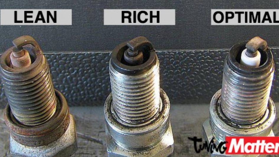
Another approach is to “read the plugs.” This means pulling the plugs after a race session and looking at the color, texture, and patterns on the ground electrode, center electrode and connected ceramics, and on the threads and ring nearest to the center electrode. The below figure from TuningMatters is a good start but there are so many other aspects to look for it boggles the mind.
It is an understatement to say that reading plugs between super rich or super lean can be compared to the black arts, voodoo, or spiritualism more than it is closer to a science. When someone reads plugs it’s like a tarot card reading experience! The person holds the plug up and turns it with a critical eye, pulling it away and then closer and then away again, turning it around and ultimately looking at the entire plug, and then uttering “Hmmmmm”…but in a way that sounds neither overly positive or negative…just largely uninformative…but it sure sounds like they have decades of experience behind that largely uninformative utterance.
By this time several more people have surrounded the “plug whisperer” waiting on baited breadth for the eventual verdict. After the verdict is read aloud, the plug owner responds with either an equally uninformative “Hmmmm” or “Oh good” depending on the mysteries solved during the plug reading ceremony. I’ve never had my tarot cards read, but I do know there are a lot of charlatans out there, and this is the case too with spark plug whisperers. It is a rare skill to read plugs correctly!
But here is the rub and the thing that really stresses me! Racecars are typically run at full throttle for as much time as possible per lap. By the time you get a plug reading after the session is over to know if the car was running lean, you may have already caused damage. All the plug whisperer does in this case is let you know you need to start thinking of how big of a bouquet to buy, magnitude of the check to write, how big of a beer you need, and how many tissues to grab. I am always amazed at the callousness of plug whisperers…they see the pain in the car owner’s face from their message and are rarely ever sympathetic and, worse, never ever even offer up a beer as consolation!
Wham, Bam, Thank you Lamb(da)!
What is a shade tree mechanic to do? If you’ve read my other investigation articles, you will see that I have a genuine lack of appreciation, patience, and enthusiasm for ambiguity. I often hear “That is just the way we do it.” or “That’s how we have always done it.” I say hogwash to that! Let’s figure this out! Why not measure the air/fuel mixture directly? How can I measure air/fuel mixture directly?
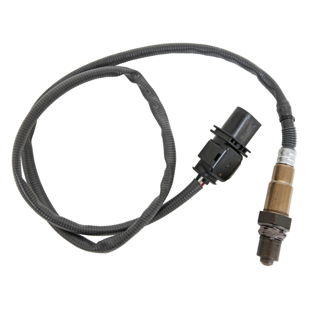
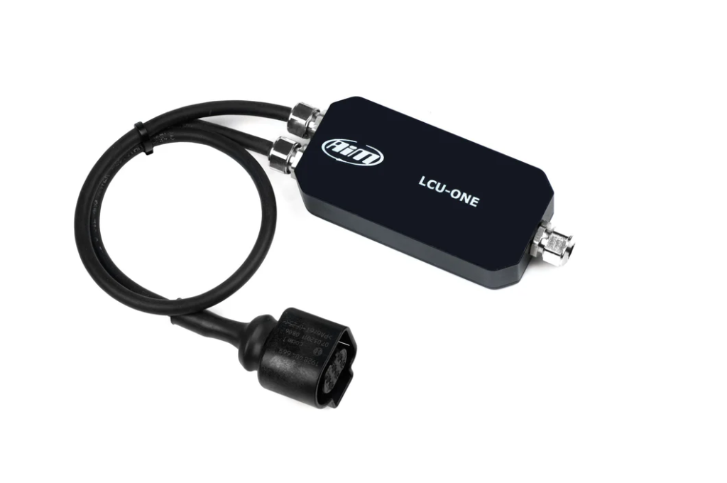
A lambda sensor does just this. The sensor consists of a probe that is positioned in the exhaust gas flow and measures residual oxygen content. Not surprisingly, these are also known, more appropriately, as oxygen sensors. Modern vehicles use lambda sensors to detect air/fuel mixture and then use that data to adjust the fuel amount to optimize mixture. Lambda sensors require a little bit of control and need to operate within a specific temperature range…a “lambda control unit” (LCU) does exactly this.
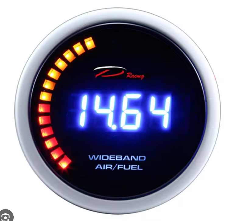
What data can a lambda sensor provide? Generally, sensors will indicate the air/fuel mixture measured as parts of air to parts of fuel with an optimal mixture being about 14.7 to 1 (It takes just a bit less than 14.7 parts of air to properly and efficiently burn 1 part of fuel. We are talking gasoline and not other types of fuel like methanol and diesel). More air than needed (higher than 14.7) results in the dreaded lean mixture that causes much crying. The figure below shows an air/fuel mixture gauge with a reading of 14.64…just about right. The lambda value expresses this mixture on a different scale with 1 being equal to 14.7 and values greater than 1 indicating a lean mixture.
Want to convert lambda values to air fuel and vice versa? Go here AFR and Lambda
Garage Testing
Well, maybe there is light at the end of the tunnel after all! Just install lambda sensors to determine mixture!
A mystery that was not resolved by reviewing manufacturer websites and other sources was how far the bungs (and sensors) should be mounted away from the head. The instructions say to mount them as close as possible to the head but not so close as to be exposed to open flame or temperatures greater than 1652 degrees. What?!! How do I determine either of these situations?! Those entirely too meager instructions seem more like CYA comments than actual or useful information.
Ultimately, I installed lambda sensor bungs on exhaust header pipes 1, 3, and 5…so that I can get data on cylinders 1, 3, and 5…which are fed by carburetors 1, 2, and 3, respectively. This sounds like an easy step but actually involved removing the headers and welding in the bungs. The bungs are about 14″ from the head which is also just before the collector for header pipes 1, 2, and 3 and collector for header pipes 4, 5, and 6. As a precaution, I also welded in bungs after both collectors in case the sensors became too hot in the closer location.
For initial testing, I installed lambda sensors in exhaust header pipes 1 and 3, labeled in the figures as LCU1-1 and LCU1-2, respectively. I tried to set up each carburetor the same as the others. Jet height was at .08″ below the bridge, float level was such that the fuel level in the jet was about 1/8 below the jet height, the slow run valve was 2.5 turns from the bottom and, then after warming up the car, idle was set at about 800 RPM.
The figure below shows the data provided by the lambda sensors when I ran the car in the garage for a few minutes. What is not seen is the earlier data where I adjusted the carbs to get both lambda values just below 1…about .98.
Two items are clearly visible. At idle the front carburetor is still a bit rich compared to the middle carburetor. Second, when RPM is raised and held there for a short period, the lambda value drops a bit which means the engine tends to go into a slightly more rich state, at least up to the ~1800 RPM tested here.
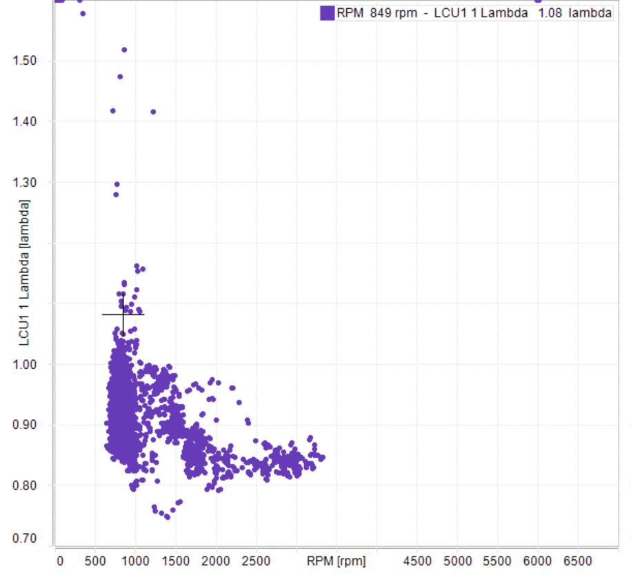
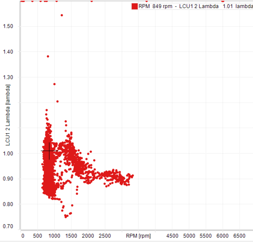
The scatter plots below present the data above in a slightly different way. Lambda values are plotted against RPM, including the data collected when I was adjusting the carburetors. The data generally show above ~2000 RPM the front carburetor is running about .84 lambda while the middle carburetor is running at about .9 lambda.
It is interesting to note that when checking jet height after adjusting the mixture, I had raised the jets to .07″ below the bridge to achieve the above mentioned lambda values at idle. A little research found that the best power is likely found with lambda values between .85 and .9, so for now I will adjust the carburetors to be similar to each other.
Garage Testing II
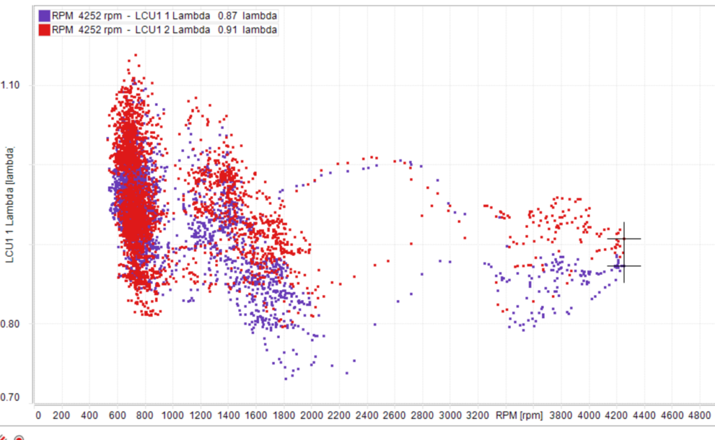
Just a little more fettling and tuning but now on the rear carb. The below data plots exhaust header pipe 1 and 5 lambda values (LCU1 1 and LCU1 2, respectively) after I adjusted the mixture of the front carb and the rear carb to get them very close to 1 at idle. The engine was run up to 4200 RPM.
The data indicate the mixture became richer with an increase in RPM, just like before, with lambda values for 1 and 5 very close to each other. The great news is that both become rich with an RPM increase which means I am moving away from flowers, checks, and beers and tears. Data collection at the track in a few weeks will be really valuable for seeing how the mixture may change across the RPM range and at full throttle.
Preliminary Findings and Next Steps
So what does this initial garage testing indicate?
- Mixture can be adjusted and successfully measured!!! Victory??!!
- The initial jet and fuel level heights were pretty good, albeit a bit rich, but I prefer this over being too lean.
Next steps?
- I am looking forward to testing throughout a greater range of RPMs, particularly between 4500 and 5800 RPM which is the normal racing range.
- If the mixture is too rich in general (particularly at race RPMs), there are several choices to lean the mixture out. The easiest is to raise the jet slightly. A challenge with this approach is the little jet adjusting screws become more and more loose as the retainer spring tension is reduced. If the screw drops out the jet will raise all the way and, you guessed it…flowers, beers, and tears. A second approach is to lower the fuel height in the jet. A third approach is to use leaner needles.
I feel like I am further away from wanting to find shards of glass. Stay tuned for further testing results.
Track Testing September 2024
Well, I am definitely not searching for shards of glass after testing at the fall VSCDA race at Road America. Also, not in search of qualified Plug Whisperers.
Collecting data with the lambda sensor was very easy…
- Just turn on power to the data system,
- Go to the screen that displays lambda sensor information (I programmed and transmitted the screen to the AIM data system prior to the event),
- Turn on power to the lambda control units,
- Wait until the lambda values appear initially as 1.0 which indicates they are on,
- Wait until the lambda values appear as 1.6 which indicate the sensors are calibrated,
- Start the vehicle, and
- Collect data.
The only downside to this process was the several minutes needed for the lambda sensors to calibrate after powering them. Several times the calibration process was not complete before needing to start the car and leave the grid.
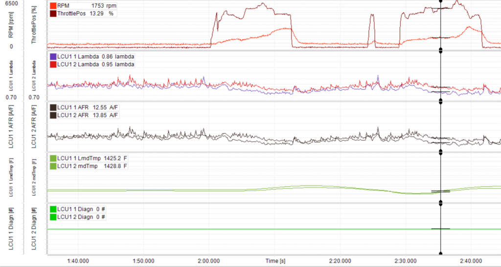
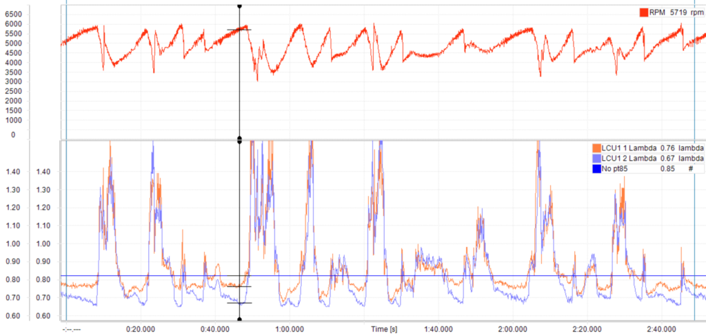
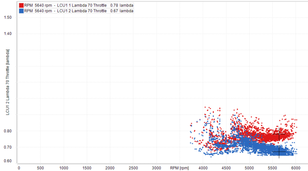
Data was collected with a lambda sensor on cylinder 5 (LCU1 2) exhaust pipe every session and on cylinder 1 (LCU1 1) in the last two sessions. The data below is from one lap during the the final session. The vertical line shows RPM and both lambda values at the very end of the full throttle segment just before starting to brake for Turn 5. The horizontal line in the lower strip references .85 lambda value.
Two immediate and apparent findings were that under high RPMs, lambda values for both 1 and 5 were below the target of .85 and 5 was consistently more rich than 1. This sounds odd but I am elated to see this because it shows I am, at least, not running lean!
OK, with those general findings, let’s go down the rabbit hole a little bit. The figure below shows header pipes 1 and 5 lambda values by RPM (LCU1 1 and LCU1 2, respectively). Note, the data was filtered so that data is only shown when the throttle was between 70% and 100% depressed. This range represents the most risky situation. The data confirm the earlier findings that both 1 and 5 were rich, very rich. A minor finding was that #1 mixture tended to become slightly more lean with increases from about 4500 – 6000 RPM and #5 showed the opposite pattern. In fact, as seen in the data, #5 was so rich it exceeded the the detection range of the lambda sensor. Overall, I am not concerned about the diverging patterns but instead more focused on correcting the overly rich mixtures.
A big question remains. How can mixture be adjusted to get closer to the ideal .85 lambda value?
It is worth noting that I adjusted carburetor 3 jet height higher (about 1/3 of a turn to the left on the mixture screw to go slightly leaner) prior to the session presented in the figures above and then compared this to an earlier session. Ideally, the bulk of the data should move toward a higher lambda value.
The left and right panes in the figure below shows pre and post jet adjustment data, respectively (again filtered to show between 70% and 100% throttle depression). There really isn’t a difference! Maybe I should have been less fearful and raised the jet height higher!?
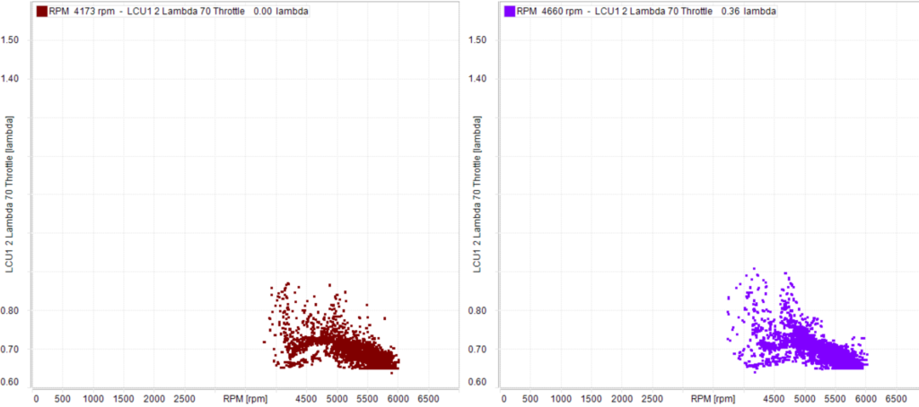
So, we are back to the earlier question. How can mixture be adjusted? Certainly more testing is needed to find out (as a side note, researchers always recommend more research)! One thought is adjusting the jet height may be beneficial but the results would only be seen at lower throttle openings…which is more like normal street driving. Perhaps when the throttle is open wide, the high air flow through the carb pulls up a tremendous amount of fuel…more than enough to be meaningfully impacted by jet height adjustments…at least relatively small ones like I implemented.
This idea is also has me questioning the value of precise fuel heights in the jets. Prior to the last session I removed the bells, springs, pistons, etc and saw that the fuel height was lower than expected in the jet…likely 3/16 or more lower than the jet! Despite the low fuel height and the raised jet…the car still ran rich. This may suggest I don’t need to stress about fuel height as long as it is not too high to pour out of the jet and not overly low to the point the the high velocity air cannot pull out any fuel.
So, if mixture is not significantly impacted by jet height or fuel height, what does impact mixture? The needles metering out the fuel become the critical element. Larger needles would likely create a markedly more lean mixture. It could very well be that after finding appropriate needles, adjustments to jet and fuel heights can be used to fine tune mixtures.
Main Findings and Next Steps
Some of the main findings…
- Lambda sensors are stupid simple to use and provide really valuable data!
- Testing when under time pressure to get on track does create challenges. Test on a dyno or a test day.
- The lambda sensors have given me peace of mind. I know the mixtures are not lean and not certainly at a point for flowers, beers, and tears.
- At least with SU carburetors, expect mixture at idle will not be predictive of mixture at high RPMs. Set mixture based on high(er) RPMs.
- Needle selection appears to be the critical factor for achieving proper mixture. More appropriate needles may reveal the sensitivity of jet and fuel height changes on mixture.
- Small adjustments in jet height did not equate to (substantial) mixture adjustments. Go big or go home? May need 1/2 turn or more to see any differences…but I need to test this.
- Precise fuel height adjustments may not be as critical as original thought. This would be wonderful! I have adjusted float levels hundreds of times trying to get them at an exact height and the same across carbs. PERHAPS NO MORE!?
- Dare I say there is no need for “Plug Whisperers?!”
- I should also add that the temperatures experienced by the lambda sensors did not exceed recommended temperatures. This means mounting them ~14″ from the head was not too close. In fact, it looks as if the internal lambda sensor heater was responsible for the ~1400+ degrees experienced by the sensor.
What’s next?
To state the obvious, given that the lambda values need to change substantially, a substantial change is needed. The first test will involve using leaner needles, likely the “standard” (UH) or even the “lean” (UL) needles. I will try to get some dyno time so that I am not testing under time pressures at a track.
A final note that I have not found the need for a four letter word when adjusting mixture using lambda sensors! I also don’t have the florist on speed dial.
Supporting Docs
- Motortrend AFR vs Lambda
- Autometer Information (what lambda values indicate rich and lean)
- FTY Racing AFR and Lambda Equivalency Values
- Engine Builder’s Oxygen Sensors and Tuning Guide
- NGK Reading Spark Plugs
- Drag Stuff Website
- Reading Spark Plugs 101 – https://www.dragstuff.com/techarticles/reading-spark-plugs.html
- Another Plugs 101 – https://www.dragstuff.com/techarticles/how-to-read-plugs.html